Touch Potential Affecting Livestock
Lawrence County, Tennessee, USA
Investigators: Carl Miller, EPRI
EquipmentUsed: 16-Channel Data-Acquisition System
Background
High levels of stray voltage were reported at a diary farm located in Lawrence County Tennessee. The dairy was concerned that touch potentials in the milking parlor were adversely affecting the livestock. To address these concerns, the local utility installed a neutral isolator (Ronk) at the serving transformer to prevent primary neutral current from flowing on the secondary neutral. A four-wire service was also installed between the transformer and the milking parlor. The objective of the investigation was to use standardized stray voltage measurement protocols to document the stray voltage levels at the dairy facility with and without the isolation device connected and to recommend follow-on actions if appropriate.
Utility Service Description
The distribution transformer of the dairy farm was supplied from a substation located approximately 11.2 miles away, as shown in Figure 1.
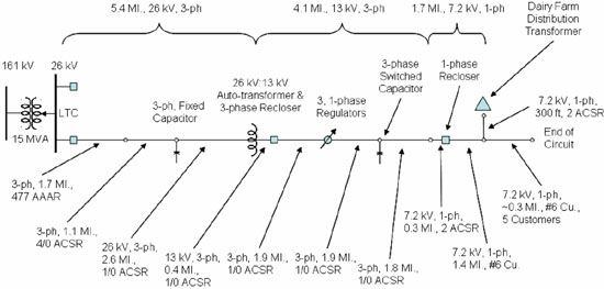 |
| Figure 1: Power System Medium-Voltage Distribution System |
The substation transforms from the 161-kV transmission voltage down to the 26- kV distribution voltage. A load tap changer (LTC) is used to control the 26-kV distribution voltage at the substation. Approximately 5.4 miles from the substation, an autotransformer is used to reduce the 26-kV distribution voltage to 13 kV. About 4.1 miles from the autotransformer, the 13-kV, three-phase system is reduced to a 7.2-kV single-phase feed to the remainder of the circuit. The single-phase tap for the dairy farm is located approximately 2 mile from the three-phase main.
Dairy Farm Description
The dairy facility is a multi-building complex served with a dedicated 25-kVA distribution transformer. The transformer, the Ronk (neutral isolator), and the CT metering co-exist on the same pole located about 125 feet into the property from the single-phase road-side primary circuit. The primary circuit continues to serve up to four more customers before the end of the line. Figure 2 shows the layout of the dairy facility.
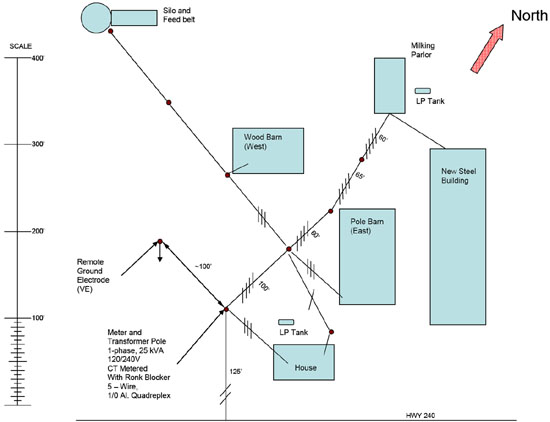 |
| Figure 2: Dairy Facility Site Layout |
A 1/0 aluminum quadruplex service runs between the meter pole and the milking parlor, as indicated by the four slashes on the lines in Figure 2. The load end of the quadruplex bare conductor is connected only to the milking parlor service panel ground bus. With the exception of the new steel building (used for baseball coaching and equipment storage), the remaining buildings utilize a three-wire triplex service connect to the three insulated conductors of the quadruplex service. The new steel building is served from a 100-A circuit breaker in the milking parlor service panel. In a follow-up visit by the local utility, it was determined that the new steel building is served with a three-wire service routed in PVC conduit from the milking parlor service panel to the steel building service building. Because the steel building service is in PVC conduit, it was assumed that the steel building service neutral is bonded to the steel building grounding electrode system. With this assumption, the new steel building may be considered served in the same manner as all the other buildings.
The milking parlor is set up to accept eight cows at a time with four cows on each side. The four milking stations on the west side of the parlor are shown in Figure 3.
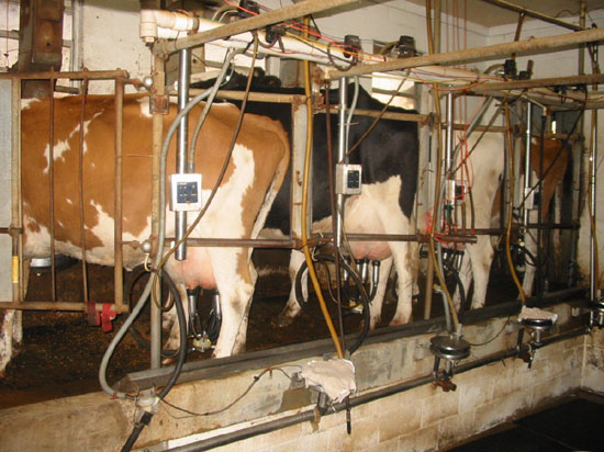 |
| Figure 3: Milking Parlor |
Inside the parlor, the stainless steel milk pipe, stanchions, and water troughs are all bonded together. The cattle floor is poured as an equipotential reference plane with bonding conductors that are bonded to the grounding conductor located on the wall behind the water troughs. There is no apparent equipotential plane established for the milking floor (as seen in the lower right-hand corner of Figure 3).
Testing
Measurements were made utilizing a 16-channel data acquisition system allowing for simultaneous collection of data points, including possible touch potentials along with meter voltage and current data. The voltage and current data allows association of touch potential with line-to-line or line-to-neutral loading. Measurements began at 3:24 PM and ended at 16.36 PM. Milking began at 4:36 PM and continued after measurements were terminated.
A number of test points were established as inputs to the data acquisition system. These test points are described in Table 1. Current test points utilized a pair of inputs to a channel in the data acquisition system. Voltage measurements were made between test point pairs connected to a data acquisition system channel. For instance to measure the voltage between the primary neutral (Np) and the remote earth electrode (EV), leads from these test points were connected to channel 1 of the data acquisition system. The resulting channel was given the name NpEV, with Np connected to the positive terminal and EV connected to the negative terminal of the channel input. A list of channel names is provided in Table 2.
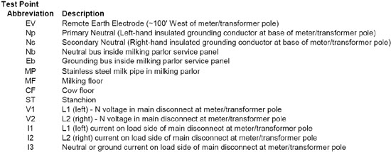 |
| Table 1: Test Point Descriptions |
 |
| Table 2: Data Acquisition System Channel Names |
A total of 25 one minute waveform records were completed during the site visit. Seven of the recordings were performed with the Ronk (neutral isolator) shorted (as if not installed). The other 18 recording were performed with the Ronk in service. From the resulting waveform data, RMS values for each cycle were calculated and averaged over the one-minute recording period. These one-minute averages are the RMS values reported in Table 3.
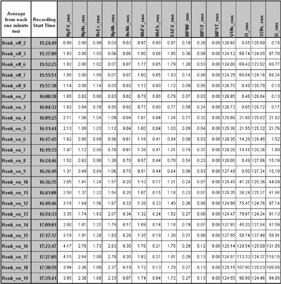 |
| Table 3: One-Minute Averaged RMS at Data Measurement Points |
Figure 4 provides evidence of the effects of the Ronk neutral isolating device. Notice the elevated parlor neutral and ground voltages referenced to remote earth while the Ronk is bypassed.
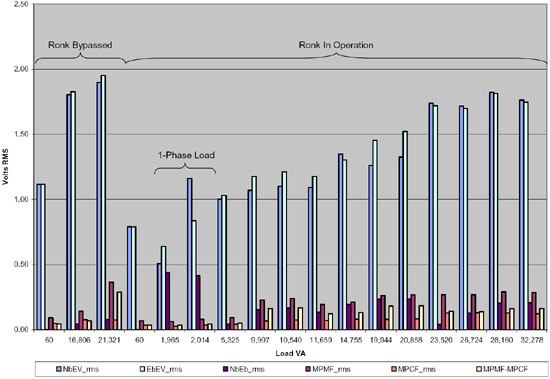 |
| Figure 4: Parlor Voltage vs. Load with Resistors On and Isolation Device In and Out of Service |
Figure 5 provides a comparison of cow contact voltages with milk parlor service panel voltages. Voltages labeled MPMF and MPCF are cow contact voltages measured across 460 ohm resistors. Cow contact voltages remain relatively low, (less than 0.3 V in all cases) and relatively constant regardless of variances in panel neutral and ground voltages.
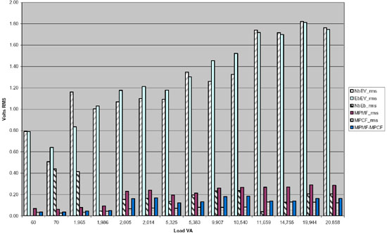 |
| Figure 5: Parlor Panel and Contact Voltages with Ronk In Service and Resistors across Cow Contact Points |
Figure 6 shows the association of cow contact potentials to both neutral current and VA loading. This chart utilizes two Y axes. The left axis is for neutral current while the right axis is for voltage values. The broad bars represent the neutral current while the narrow bars represent cow contact voltages measured across 460-ohm resistors. The largest cow contact voltage (MPMF) is measured between the milking pipe and milking floor. There is no obvious correlation of cow contact voltages with neutral loading. Comparing cow contact voltages with VA loading on the X axis suggests cow contact voltage are somewhat load-dependent. However, once the load goes above 9,000 VA, there is no significant change in cow contact voltage levels as VA loading increases. Close inspection of the data used to create Figure 6 indicates that all loading above 9,000 VA and all MPMF values above 0.15 V occurred after 4:30 PM.
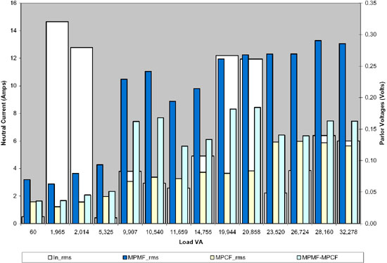 |
| Figure 6: Parlor Contact Voltages Associated With Load VA and Neutral Current |
Several times during the testing the resistors across the cow contact measurement points were switched on and off for the same load condition. The purpose of this procedure is to be certain that a measured voltage has enough source strength to drive a current through a resistance and to show the importance of making cow contact measurements across a load simulating either a cow or a human. Figure 7 shows that when the 460-ohm resistors are in the circuit the cow contact voltages are significantly lower than when the resistors are not used. It should be noted that the literature on stray voltage measurement protocols is very explicit in stating that a resistor should be used to perform measurements for 60-Hz stray voltage.
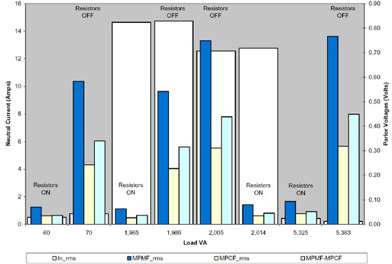 |
| Figure 7: Parlor Contact Voltages Associated With Load VA and Neutral Current Where Cow Contact Resistors Were Switched |
Various studies have shown that cows are typically only sensitive to currents above 4 mA. Cow contact current may be calculated by dividing the contact voltage by the resistance across the contact voltage. Table 4 shows the maximum cow contact voltages measured where resistors were switched and the neutral isolation device was in service. Based on the measured resistances and voltage levels, the associated current levels were calculated. The resulting maximum current of 0.63 mA is well below values reported to cause cow response.
 |
| Table 4: Maximum Recorded Cow Contact Voltages and Calculated Currents |
Conclusions
The Ronk neutral isolation device is providing expected isolation between transformer primary and secondary neutrals. With the neutral isolator in-service, results show that cow contact voltages and associated currents are below reported cow sensitivity levels.
Although test results do not indicate cow contact voltage problems, it should be noted that testing was performed immediately after a rain storm, which can increase ground conductivity. Follow-on testing should be considered to confirm some of the measurements in this report and testing should be considered after the changes are made to validate voltage cow contact voltage levels. Before follow-up testing is performed the following changes or assurances should be made:
- Ensure that all parlor stanchions, milk-pipes, watering troughs, and floor grids are bonded together and a single grounding conductor provided to bond the listed items to the panel ground.
- Ensure that the well casing ground is bonded only to the parlor panel ground.
- Ensure that the ground electrode located outside of the parlor at the parlor drain output is bonded only to the parlor panel ground.
- Ensure that the service from parlor panel to new steel building is a three-wire service (two lines and one Ensure neutral in PVC conduit).
- Inside parlor panel, ensure that the steel building branch circuit neutral is connected only to the parlor panel neutral bus.
- Inside the steel building panel, ensure that the service neutral is bonded to the steel building grounding electrode system.
- In lieu of 4), 5), and 6), replace new steel building service from the parlor with a three-wire service directly off the quadraplex service drop and establish a neutral-to-ground bond inside new steel building service panel.
- Establish a ground-reference-grid on milking floor (pit floor), bonding the grid to the cow floor ground-reference-grid, stanchions, and milk-pipe.
Follow-up testing should include key measurements and conditions used in this case study to establish a new baseline. Once the new baseline is established, additional testing may be conducted to see the impact of changes, such as the installation of an isolation transformer. The results of this testing should establish recommendations on whether an isolation transformer is needed for the milking parlor.

