Measurement Protocols
Stray and Contact voltage shock complaint scenarios range across a broad spectrum, from urban sidewalks and community playgrounds, to farms, swimming pools, and marinas. As such, there is no single leading practice on the measurement equipment or the evaluation protocols to use when diagnosing the source of the voltage. To address this industry challenge, EPRI and the IEEE have collaborated on an industry consensus document titled: IEEE 1695-2016 - IEEE Guide to Understanding, Diagnosing, and Mitigating Stray and Contact Voltage. This guide supplies a diverse selection of investigative procedures and the equipment to be used for each investigation type. EPRI also has a selection of publicly available documents on these topics such as EPRI Report 1020096, Guidebook for Evaluating Elevated Neutral-to-Earth and Contact Voltages in Distribution Systems - Part 1: Swimming Pools, Water Bodies, and Other Wet Areas. A distillation of these documents yields a conclusion that measurements of AC voltage difference, AC current flow, conductive objects continuity (i.e. resistance), and/or electric field strength are the key diagnostic requirements. These four measurement considerations cover nearly any scenario of interest when the correct measurement procedure is applied to a complaint investigation. The following materials discuss two of the most common and the most challenging measurement environments to consider urban location and water bodies.
In 2004, the EPRI research plan identified five areas of opportunity where supplemental or new research was needed. These five areas included test and measurement protocols, modeling and simulation guidelines, test equipment and mitigation methods assessments, technology transfer, and regulatory guidance. Of these five areas, consistent and repeatable measurement protocols are a fundamental building block to each of the other areas of interest.
The intent of this section of the Web site is to define procedures and measurement equipment suitable for conducting consistent and repeatable stray voltage assessments.
Recognizing that excellent measurement protocols and procedures exist for some situations--such as animal contact area measurements--there are many inconsistencies and differences in the procedures used to conduct stray voltage assessments across many of the other areas of interest--such as swimming pools--and for energized objects in urban areas. To that end, the material presented herein provides recommendations for assessment protocols across three areas of interest:
- Residential areas where elevated voltage potentials are experienced near swimming pools, hot tubs, faucets, and other residential contact points.
- Dairy, swine, and poultry farms where elevated voltage potentials are experienced at animal-feeding, production, and other contact points.
- Faulted secondary phase conductors coming in contact with a metallic object that can be subsequently contacted by humans or animals.
Generally speaking, the areas of importance for performing proper measurements include the following:
Test and Measurement Equipment | Safety and other Fundamental Measurement Objectives | Animal Contact Area Measurements | Residential Contact Area Measurements | Energized Metallic Object Contact Area Measurements | Useful Documents, References, and Links to Measurement Procedures and Equipment
Test and Measurement Equipment
The stray voltage investigator must be versatile and familiar with a wide assortment of test and measurement equipment in order to diagnose the source(s) of the voltage concern. A wide variety of measuring equipment is available to support the stray voltage investigator. The challenge is in selecting the most appropriate instrumentation for a given test or measurement. The intent of this section is to provide you with an overview of the types of measurements of interest, the available equipment, its functions, capabilities, and suitability for field use. The chapter is subdivided into five main clauses:
- Considerations for performing voltage measurements.
- Considerations for performing current measurements.
- Considerations for taking single snapshots of the voltages and currents versus the value of longer-term trending.
- Supplemental measurement and diagnostic equipment that should be part of the toolkit of any stray voltage investigator.
- Considerations for accurate measurements and equipment-calibration requirements.
Voltage Measurements
Accurate measurements of voltage potentials at human and animal contact points are essential to the stray voltage investigation. The challenge is that measurement resolution down to the tenths of a volt must be accomplished, and an error of just a few tenth of a volt can result in the difference between no action required and expensive mitigation requirements. This section contains trademarked names and references to specific brands of metering equipment. However, these callouts are simply for reference and in no way imply endorsement of that particular brand.
AC Voltmeters
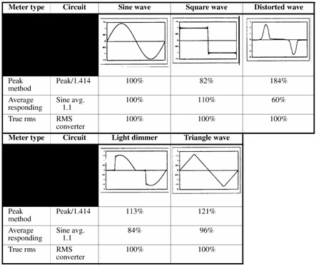
It is recommended practice that all readings be taken with "true RMS" responding voltmeters. True RMS reading voltmeter indicates the square root of the sum of the squares of all instantaneous values of the cyclical voltage waveform. These meters will indicate the correct or true RMS value for every type of waveform from sinusoidal waves to pure square waves. Therefore, they are the preferred voltage-measuring instrument for a stray voltage survey.
Average-responding RMS voltmeters and peak-responding voltmeters are not recommended because they assume a sinusoidal waveform and calculate the RMS equivalent based on that assumption. With the average-responding voltmeter, a multiplier called the form factor is used to convert the averaged value to the equivalent RMS value. The 1.1 multiplier used by these instruments is based on the assumption that the RMS value of a sine wave is 1.1 times the average value of the same rectified sine wave. With peak-responding voltmeters, the peak value of the waveform is detected and a 0.707 multiplier is used to convert the peak value to the equivalent RMS value. Like the average responding circuit, the waveform must be sinusoidal or the displayed value will be erroneous.
The following table shows several waveshapes and the percent error recorded by the peak and averaging responding meters. This emphasizes the importance of using a true rms meter.
Table 1
Percent Error vs Type of Instrument Used for Differing Waveforms
DC Voltmeters
The true RMS voltmeters suitable for measuring AC voltage are typically suitable for measuring DC voltage as well. When performing a comprehensive stray voltage assessment, it is recommended practice to record both the AC voltage and the DC voltage across the contact points of interest.
Current Measurements
AC current measurements are slightly more difficult to perform during a site survey compared to voltage measurements, but there are many instruments available to simplify the process. As with voltage measurements, recommended practice is to use true RMS-reading meters when performing a site survey. True RMS ammeters include two types of indirect reading ammeters: current transformers and Hall-effect types.
Current-transformer (CT) ammeters: A transformer is commonly used to convert the current being measured to a proportionately smaller current for measurement by an AC ammeter. There is very little resistive loading with these ammeters, and when a split-core transformer is used, the circuit to be measured is not interrupted. Clamp-on CTs cannot be used to measure DC currents. Caution is recommended when interpreting readings obtained with a CT device because some of these ammeters may not be true-RMS-reading meters. Sensitivity wise, the CT must be capable of measuring accurately in the milliampere range. For current measurements, the investigator may need multiple CTs to cover a range of currents from one milliampere flowing into the earth via a ground rod to as much as a few hundred amperes on a circuit phase conductor.
Hall-effect ammeters: The Hall effect is the ability of semiconductor material to generate a voltage proportional to the current passed through the semiconductor, in the presence of a magnetic field. This is a "three-dimensional" effect, with the current flowing along the X axis, the magnetic field along the Y axis, and the voltage along the Z axis. The generated voltage is polarized so that the polarity of the current can be determined. Both AC and DC currents can be measured.
Additional Measurement Considerations
Spectral Content (Harmonics)
There are a number of documented cases where an elevated NEV concern is caused by harmonic currents flowing through the neutral conductor of the power distribution system and the earth. Because these currents do not cancel like the 60-Hz currents, they can be the dominant component in some NEV investigations. A true RMS meter will quantify the total voltage, but a harmonic analyzer with resolution to capture frequencies out to at least the 50th harmonic (3,000 Hz) must be used to determine the harmonic content and the individual harmonic contributions. It is therefore useful in some instances to measure the harmonic spectrum for stray voltage investigations where the suspected source is a multi-phase wye-grounded distribution system or where the suspected source of the elevated NEV is from customer equipment.
Peak versus RMS
Animals and humans respond to the peak of the voltage waveform in terms of the related current flow through the body. Most recommended limits or levels of concern are based on a conversion to the equivalent RMS value. When capturing peak values, it is recommend practice to either capture the associated waveform or if the meter is not capable of waveform capture to ensure the meter is set to record the instantaneous millisecond peak and not an average over multiple cycles.
Event Duration Considerations
For the purposes of this document, the duration of a voltage or current variation will be defined per recommendations from IEEE std 1159-1995 Recommended Practice on Monitoring Electric Power Quality, for:
- Transients
- Short-duration RMS variations
- Long-duration RMS variations
where transient events are in the millisecond range and RMS variations last at least one half of an electrical cycle. The RMS variations are then subdivided into short duration variations lasting less than 2 minutes and long duration variations lasting 2 minutes or more. It is the RMS variations and most particularly the long-duration RMS variations that are of most interest for the stray voltage investigator. When taking voltage readings, it is a recommended practice to take several readings over a few minutes to confirm that the readings are fairly consistent.
Trending Equipment versus Snapshots
Depending upon the type of investigation, there may be a need to trend data over several weeks. A number of data loggers (either voltage or current) are available to accomplish this. In certain situations, a single snapshot of the voltage or the current is inadequate. For example, as the loading of a distribution system varies during the day, the NEV contribution from the distribution system can change proportionally. For distribution-induced NEV, the major contribution is due to the non-canceling currents (unbalance and triplen harmonics) flowing on the distribution neutral conductor. By logging 15-minute snapshots at a contact point and comparing this to 15-minute loading data, comparisons can be easily made to rule out or to confirm potential causes. Example products that are useful to conduct snapshot measurements and data logging include the MetrosonicsTM SRV-4 and the AEMCTM L205.
Other Diagnostic Equipment
The stray voltage investigator may sometimes find useful additional diagnostic equipment to accomplish the objectives of the audit. These other devices are described in the following sections to include both function and suitability for various types of investigations.
Non-Contact AC Voltage Tester (Pen Light)
Several manufacturers supply non-contact capacitive voltage testers suitable to determine whether AC voltage greater than the specified voltage is present on an object that can become energized. Care should be taken to closely evaluate the data sheets because each of the devices has a different sensitivity range (anywhere from 5 volts to 50 or 100 volts), but they do allow the investigator to detect and cautiously deal with objects that may become energized, such as street lamp posts, manhole covers, service boxes, conduits, and concrete.
The preferred units come with a test capability to ensure that the indicator light glows or an audible alarm sounds when placed near an energized object. Example companies that manufacture low-voltage (less than 24-volt sensing) versions of these non-contact AC voltage testers are ExtechTM and FlukeTM. These testers are suitable for determining the presence of AC voltage but are not suitable for accurately measuring the value of the AC voltage.
Load Boxes
For investigations of both residential animal stray voltages, a load box capable of testing 240 volt and 120 volt secondary systems is useful. These load boxes contain switchable resistors and allow the facility load to be shut off while the box is connected to determine the value of NEV contributed as the load is varied. This method also enables a way to determine resistances of the secondary neutral conductor via phase-to-neutral loading and a way to determine facility load NEV contributions of the service transformer primary neutral grounding point via line-to-line loading.
Test Resistors
Test resistors provide a means of determining whether the voltage source is capable of driving adequate current between two contact points. The literature and the test protocols describe 500-ohm and 1,000- and 20,000-ohm test resistor configurations. These are relatively easy to obtain and can be built into a switchable configuration for banana jack connection to a voltmeter.
Metal Detectors
For location of metallic pipes, conduits, and other potential sources of stray voltage, a metal detector can provide the investigator with a useful tool for identifying these sources.
Earth Ground Resistance Testers
The resistance of the earth grounding electrode can be tested with a ground resistance tester. The ground resistance tester injects a known voltage at a known frequency and measures the current driven by the known voltage. With the voltage and current known, the resistance is easily calculated.
Other Miscellaneous Hardware
Other miscellaneous hardware that may be useful to an investigator include:
- Metallic plates come in handy not only for measurement at animal contact areas but also around swimming pools, where one meter lead is attached to the plate and the plate is placed on wetted cement to form a good contact surface. Steel and copper plates of roughly 18 square inches are successfully used in the field by investigators.
- Large bobbers or floats are useful for investigations of shocking at swimming pools and boat docks, where the float is attached to one of the meter leads and placed in the water.
- A long steel screwdriver can provide a reasonably accurate ground reference reading but is not recommended when precision is important.
- A copper screw-type rod (similar to those used to ground a bucket truck) can be useful. For documented readings or in sandy soil, it is desirable to use this type of ground reference and attempt to obtain a minimum penetration of at least two feet into the earth.
- A watch is often very important to record the time when a measurement was obtained to correlate with power system loading or with other readings taken at different points on a circuit.
- Wire in 100-foot spools is extremely handy when attempting to simultaneously obtain readings from multiple locations or when trying to reach a remote ground reference point.
- A digital camera is used to document and report physical aspects of the site and to validate compliance or non-compliance to applicable codes such as proper wiring, service bonding, and presence of grounding electrode(s).
Safety and other Fundamental Measurement Objectives
The following sections will detail the common elements of the investigation, including:
- Safety precautions to be used.
- Methods to ensure accurate measurements.
- Considerations for measurements that can assist in defining the source.
Safety Precautions
Measurements of electrical quantities where the electric power system supplies the energization source have some common safety precautions as follows:
Measurements of energized metallic objects should be attempted only by persons with appropriate electrical safety training and experience and with proper safety gear. Workers involved in testing energized objects should abide by the prescriptions of NFPA 70E, concerning appropriate protective equipment, as well as government regulation codified in OSHA CFR 1910 and CFR 1926 and in the National Electrical Safety Code® (NESC)® (Accredited Standards Committee C2).
Workers trained in performing any of the prescribed measurements throughout this document should consider training and abide by the appropriate utility safety documents related to:
- Use of proper personal protective equipment.
- Work area protection.
- Hazard communication.
- First aid CPR.
- The proper use of voltage detectors and meters.
- Working near electric sources.
- Others as deemed necessary by local, state, provinicial, or federal regulations.
When entering enclosures and manholes, there are other specific safety considerations that should be followed, such as the use of barricades and gas detectors.
Basic Measurement Considerations
Common measurement considerations for performing a voltage investigation involve the following:
- Identification of the shock complaint location(s).
- Determination of the presence of a voltage at the shock complaint location.
- Identification of a "common" reference point.
- Calibration considerations.
Identification of the Shock Complaint Location(s)
This can typically be accomplished before the assessment takes place based on a question-and-answer session. Depending on the identified location, the equipment list may vary. In any event, the location description should allow the investigator to understand the materials and equipment to bring along. It is important to set some communication expectations regarding what will be done and how the results of the investigation will be recorded or reported.
Determination of the Presence of a Voltage at the Shock Complaint Location
It should be emphasized that the level of voltage present on an energized object or at a neutral-to-ground bonding point will vary with weather conditions, circuit loading, intermittent contact of a faulted conductor, and even the photo sensors in lighting systems. When a complaint is received, every attempt should be made to thoroughly investigate the complaint area to determine the possibility of an intermittent problem. A voltage logger may be needed to further quantify intermittent voltages. Specific examples where voltage may be intermittently present include:
- High-impedance faults due to power system conductors touching an object that can become energized.
- Photo sensors in street lights that allow voltage to appear only when the photo-eye is in the closed "on" position.
- Loading levels of the power system neutral conductor where an objectionable NEV exists only during peak times of the day.
Identification of a "Common" Reference Point
The remote earth reference point can be variable depending upon currents flowing through the earth at the point selected as the remote reference. The general rule is to select a remote reference point at least three to four times the distance of the length of the neutral-to-ground bonding ground rods for NEV measurements. Alternatively, one can move the remote earth meter probe further away from the point of connection of the other probe connection point until a non-changing reading is obtained. For energized objects, the distance is not significant as long as a solid connection to a reference ground such as a neutral lug or solidly grounded metallic object is located, but it should be noted that the selected ground reference may or may not be at ground potential.
Advanced measurement considerations when a voltage source has been identified include:
- No load versus resistive load voltage.
- Current flow.
- Spectral content.
No Load vs Resistive Load Voltage
It is a recommended practice to use a load resistor to confirm that a measured voltage actually has a source impedance that is low enough to drive currents through the resistor. A 500-ohm, 1,000-ohm, or a 20,000-ohm resistors are commonly used values, depending on the protocol.
Current Flow
A properly rated current transducer in conjunction with the measured voltage on a pole down ground can accommodate some useful determinations of earth resistances, relative NEV values, and possible broken or high-impedance neutral connections along a circuit. Additionally, knowing the currents and phase angles of the current-carrying phase conductors and knowing the neutral current value will yield a good representation of the current flowing in the earth at the measurement point.
Spectral Content
The use of a harmonics analyzer to record RMS and harmonic content of the voltages and currents has been found to be extremely valuable in terms of understanding sources of elevated voltage levels and potentially even somefaults related to an energized object conductor.
Calibration and Calibration Verifications
Not all contact voltage measurements require extreme accuracy. However, when the measurements do require accuracy for comparison to limits or levels of concern, the calibration status of the measurement equipment can be a consideration. This is especially applicable for animal contact areas and for wet-area shock complaints, where just a few tenths of a volt can be important.
Because most of the measurement instruments are portable and the equipment and test leads may be exposed to dirt, sand, pool chemicals, and inclement weather on a regular basis, the calibration and maintenance schedule may need to be adjusted to reflect their usage conditions. When the measurements are just to confirm the presence or absence of a voltage, this is not an issue, but when they require "for-the-record" accuracy, it is useful to ensure that the equipment to be used is confirmed to be accurate and in calibration. It is also useful to have "data forms" with a place to record serial numbers and relevant calibration information for the instrumentation used during the investigation. These records are valuable when disputes arise after the fact and an accurate record is needed pertaining to measurements before and after mitigation has been applied.
Optionally, for organizations performing measurements related to human and animal contact on a regular basis, it is may be useful to consider building a "calibration validation" box to provide reference signals for AC and DC voltages and currents. These boxes can quickly determine the accuracy of the metering equipment without having to send the device out for calibration. Other equipment, such as clamp-on resistance meters, usually come equipped with calibration-verification resistance loops. These resistance loops can be used in the field to verify the accuracy of the resistance measurements.
Animal Contact Area Measurements
The impact of stray voltage on animals has been suspected since the 1950s. However, it was not until the late 1970s and early 1980s that the subject began to receive national attention. Most of the basic investigative and measurement procedures emerged during the 1980s, although learning and refinement continues.
Efforts to understand and prevent the shocking of farm animals have been very comprehensive, including animal testing, field measurements, recommendations on levels of concern, implementation of solutions, and many technology-transfer workshops. Much of the research has centered on dairy cows because of the high costs associated with the loss of milk production, but there have also been studies on swine facilities and poultry farms.
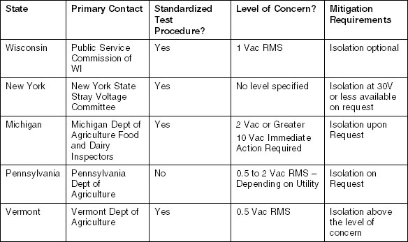
Certain states (as listed in Table 2) have published levels of concern upon which remedial actions must be pursued. For example, the Wisconsin Public Service Commission (PSC) has recommended maximum voltage levels for animal-contact areas, based upon substantial dairy cow testing which suggests that the perception threshold for nearly all dairy cows tested was greater than or equal to 4 milliamps (derived from a 60HZ ac voltage source). The level of concern is translated based on a 500 ohm specified animal resistance to yield 2 Vac rms as the published level of concern. With this level in mind, the PSC has set the level of concern at one half of that value or “one-volt ac rms.” When more that one-half volt as measured at an animal contact point can be attributed to the utility primary system remedial actions should be implemented to reduce the level of stray voltage. With such a small level of concern, it is important to insure that proper measurement protocols are used and calibration verifications on the measurement equipment are implemented.
Table 2
Published Levels of Concern by State
Test Protocol
The test protocol as published by the Public Service Commission of Wisconsin has been thoroughly tested and review by the EPRI team responsible for developing this measurement protocol information. Recommended practice is to use the Wisconsin test protocol for farm-related investigations. A copy of this document is available at:
https://psc.wi.gov/Pages/Programs/StrayVoltageHomePage.aspx 
The detailed protocol in the Wisconsin publication provided the procedures and forms for the investigation. The following sections provide supplemental information to use in conjunction with the protocol to assist the investigator.
Objectives
The basic objectives of the investigation are to ultimately determine:
- The presence or absence of a stray voltage and/or NEV at various locations on the farm.
- The presence or absence of proper bonding at the subject locations.
- The sources of the measured voltages at the subject locations.
- The requirements (if any) to perform remedial actions to reduce voltage levels.
Equipment/Materials Needed
Recommended equipment for the on-farm investigation includes:
Basic:
- Resistors: 500 ohm and 1000 ohm
- True RMS meters capable of, AC and DC voltage/current measurements
- Remote earthing rod
- Metal plate
- Ground resistance meter
- Several 200-foot wire spools
- 120V/240V load box
- Recording forms
Advanced:
- Voltage trending equipment
- Harmonics analyzer
- Gauss meter
Measurement Protocol
Following the PSC Wisconsin Protocol, the investigator should be able to adequately measure stray voltage quantitiesrelated to animal contact. The procedure essentially establishes baseline and worst-case measurements where the objective is to be able to determine the utility primary neutral contribution to the stray voltage at the animal contact point, the farm load contribution, and possible equipment contributions.
The basic measurements involved in the protocol will define:
- The voltage for the utility primary neutral with respect to a remote earth reference.
- The voltage for the neutral of the building under investigation with respect to the remote earth reference.
- The animal contact point voltage.
Residential Contact Area Measurements
Reports of shocking at swimming pools, hot tubs, showers, and faucets have been common since the 1970s, but the subject was not readily discussed in a collaborative way and utilities did not share cases until the 1990s. Most of the investigative and measurement procedures were developed in the 1980s, and refinements continue today. Key causes of such shock hazards include:
- Metallic parts not being properly bonded per requirements of the National Electrical Code (NEC).
- Unbalanced voltages on the distribution circuit.
- High currents through a neutral impedance.
- Customer load faults.
- Open neutral conductors and connections.
The efforts to identify and resolve shock hazards at swimming pools and hot tubs include field measurements, information on human perception (levels of concern), implementation of solutions, and a number of papers and documents related to cause and remedy.
This section details the measurement protocols and procedures for measurements at service panels, swimming pools, hot tubs, water faucets, and conduits.
Procedure
The following are options and subsequent examples of the type of investigative procedure that proves useful for residential wet-area contact locations. All listed steps may not need to be performed, depending on the specifics of the complaint.
- Review the audit plan and checklist of information to be obtained. These are written notes and objectives developed by the investigation team.
- Meet with the affected party (if possible) to obtain necessary access permissions and articulate the objectives of the investigation, noting that the primary purpose of this visit is to obtain a clear understanding of the complaint and the source of the complaint.
- Visual inspection: Prior to making measurements, perform a visual inspection starting with the location of the contact complaint and systematically moving upstream to sub-panels, main panels, neutral grounding points, meter bases, service transformers, and distribution circuit points as deemed necessary to understand the magnitude of the complaint. This allows the investigative team to note any abnormal conditions identified and other items for follow-on investigation. The suitability of obtaining voltage and current readings at the points of interest should also be noted during the visual inspection. Optionally, the visual inspection may involve a digital camera for documentation purposes during this step.
- Field measurements: The following sub-listing provides field experience on some of the possible options for measurements that may be useful in the diagnostic steps of the investigation:
a. At the contact complaint point: Measure voltage between contact complaint points with and without a 500-ohm load resistor, current with a 500-ohm load resistor, and voltage (or resistance) between any parts that are required to be bonded by local codes. Confirm the presence of rebar in any cemented areas involved with the contact location.
b. At applicable sub panels: Measure the voltage between all conductor combinations to validate proper wiring, the voltage from neutral to remote earth, and the voltage at the panel casing to remote earth. Measure the voltage (or resistance) between any parts that are required to be bonded by local codes.
c. At main service panel: Measure the voltage between all conductor combinations to validate proper wiring, the voltage from neutral to remote earth, the voltage at the grounding electrode to remote earth, and the voltage at the panel casing to remote earth. Measure the voltage (or resistance) between any parts that are required to be bonded by local codes. Also measure the impedance of the main grounding electrode conductor.
d. At meter base: Measure the voltage from the ground electrode to remote earth and at the panel casing to remote earth. Measure the impedance of main ground electrode.
e. At telephone and cable service entrances: Check the continuity between ground and main service ground electrode.
f. At water service entrance: Check the continuity between water pipes and the main service ground electrode. Measure the voltage from water pipes to remote earth.
g. At gas service entrance: Measure the voltage from the main gas-line side to remote earth, across metering point, at the source side to end-use side, and at the end-use side to remote earth.
h. At main service transformer: Measure the voltage ground electrode to remote earth, the current on ground electrode, and the impedance of the ground electrode. Optionally, measure the voltage at remote earth. The current flow may be measured for telephone and cable shields.
i. At other feeder neutral-to-ground bonding points: Measure the voltage ground electrode to remote earth, the currents on the ground electrode, and the loading on phase and neutral conductors. Measure the impedance of the main ground electrode.
j. At capacitor bank locations: Measure the voltage from phase to phase, the voltage at the ground electrode to remote earth, currents through the loading phases and neutrals, and current at capacitor fuse links and ground electrodes.
k. At multi-circuit neutral interconnections points: Measure the voltage at the ground electrode to remote earth and currents through the loading phases and neutrals.
l. At substations: measure the voltage at neutral risers to remote earth, the voltages from phase to phase and from phase to ground, currents on phases and riser, and currents at transformer grounds and XO bushings
Measuring the Voltage Between Pool (or Hot Tub) Water and Ladder Steps or Handrail
Figure 1 shows how to measure the voltage between a pool of water and ladder steps or a handrail.

Figure 1
Measuring Voltage Between Pool Water and Ladder Steps or Handrail
Suggested Equipment and Materials
- Non-contact AC voltage indicator
- High-impedance true RMS AC multi-meter
- Harmonics analyzer (optional)
- T-Handled twist-type grounding rod or large screw driver
- Recording forms
- Watch
- Personnel protective equipment
- Digital camera
- Wire spools
- Load resistors
- Electricians' tool box
- Shovel or gardening spade
Procedure
- Wet the concrete area around the ladder or handrail supports.
- Drop the "+" probe of the AC voltmeter in the pool water. Caution: To prevent damage to the voltmeter probe, use a short length of wire attached to the "+" probe to dip into the water.
- Place the "-" meter probe against the metal of the ladder or handrail to measure the voltage between it and the pool water.
- Measure the voltage between the pool water and the ladder/handrail supports.
- Record the measurements and time of day when they were taken.
- Repeat steps 1 through 5 for each ladder or handrail indicated as a shocking voltage location by the customer.
- Optionally repeat entire process with DC voltmeter.
- Optionally repeat entire process with a harmonics analyzer and save the voltage-spectrum data.
- Repeat enough steps with a load resistor to confirm a non-varying (stiff) voltage source.
Measuring Voltage Between Pool Water and Coping Stone
Figure 2 shows how to measure the voltage between a pool of water and coping stone.

Figure 2
Measuring Voltage Between Pool Water and Coping Stone
Procedure
- Make a top-view (or plan-view) sketch of the swimming pool, noting each section of coping stone around its edge.
- Find a scratch or small spot of exposed metal on a section of coping stone.
- Drop the "+" probe of the AC voltmeter in the pool water. Caution: To prevent damage to the voltmeter probe, use a short length of wire attached to the "+" probe to dip into the water.
- Measure the voltage between the pool water and the bare spot on the coping stone.
- Record the reading and time of day on your sketch.
- Repeat for each section of coping stone in areas indicated as shocking voltage locations by customer.
- Optionally repeat steps 2 through 6 with a DC voltmeter.
- Optionally repeat steps 2 through 6 with a harmonics analyzer and save the voltage-spectrum data.
- Repeat enough steps with a load resistor to confirm a non-varying (stiff) voltage source.
Measuring Voltage Between Pool Water and Concrete Deck
Figure 3 shows how to measure the voltage between a pool of water and a concrete deck.
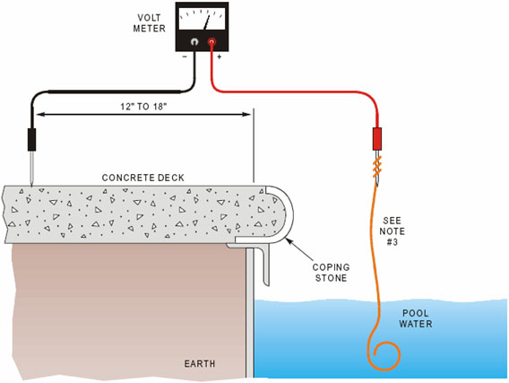
Figure 3
Measuring Voltage Between Pool Water and Concrete Deck
Procedure
- Wet the concrete deck.
- Drop the "+" probe of the AC voltmeter in the pool water. Caution: To prevent damage to the voltmeter probe, use a short length of bare wire attached to the "+" probe to dip into the water.
- Place the "-" voltmeter probe on the wet concrete deck, 12 to 18 inches from edge of pool (clear of coping stone).
- Measure voltage from the pool water to the wet concrete deck.
- Record voltage reading and time of day when it was taken.
- Optionally repeat steps 2 through 5 with a DC voltmeter.
- Optionally repeat steps 2 through 5 with a harmonics analyzer and save the voltage-spectrum data.
- Repeat enough steps with a load resistor to confirm a non-varying (stiff) voltage source.
Measuring Voltage Between a Water Faucet and Earth
Figure 4 shows how to measure the voltage between a water faucet and earth.
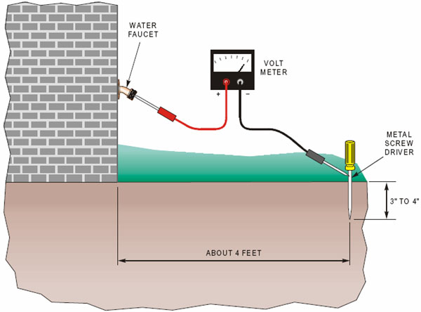
Figure 4
Measuring Voltage Between a Water Faucet and Earth
Procedure
- Push a metal screwdriver into the ground to a depth of 3 or 4 inches, approximately 4 feet from the water faucet.
- Place the "-" probe of the AC voltmeter against the screwdriver and the "+" probe on the faucet.
- With a high-impedance AC voltmeter, measure the voltage from the screwdriver to the water faucet.
- Record the measurement and time of day when it was taken.
- Repeat steps 2 through 4 with a DC voltmeter.
- Repeat steps 2 through 4 with a harmonics analyzer and save the voltage-spectrum data.
- Repeat enough steps with a load resistor to confirm a non-varying (stiff) voltage source.
Measuring Voltage Between Pole Ground and Earth
Figure 5 shows how to measure the voltage between a pole down ground and earth.

Figure 5
Measuring Voltage Between a Pole Down Ground and Earth
Procedure
- Push a metal screwdriver into the ground to a depth of 3 or 4 inches, approximately 4 feet away from the power pole. Note: When pushing the screwdriver into the ground, do not let it contact the pole's ground rod, down guys, primary and secondary cables, metal pipes, or any other obstructions that might influence the voltage measurement.
- With a high-impedance AC voltmeter, measure the voltage from the screwdriver to the pole ground.
- Record the measurement and the time when it was taken.
- Move the screwdriver 45 degrees around the pole from its initial location, push it into the ground, and take another voltage measurement to verify the first one, as shown in Figure 6.
- Record the second measurement and the time when it was taken.
- Optionally repeat steps 2 through 5 with a DC voltmeter.
- Optionally repeat steps 2 and 3 with a harmonics analyzer and measure and save voltage-spectrum data.
- Repeat enough steps with a load resistor to confirm a non-varying (stiff) voltage source.
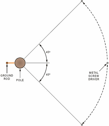
Figure 6
Making Multiple Measurements to Insure Accuracy in the Readings
Measuring Voltage Between an Air Duct and Earth
Figure 7 shows how to measure the voltage between an air duct and earth.
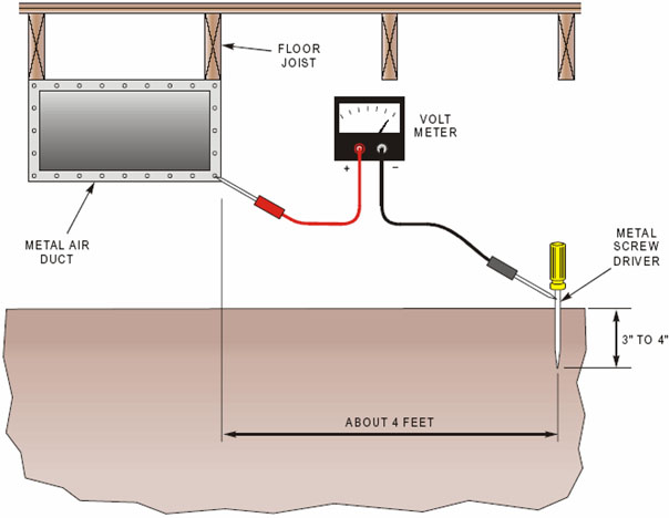
Figure 7
Measuring Voltage Between an Air Duct and Earth
Materials Needed
- High-impedance AC multimeter
- Screwdriver or screw type ground rod
- Recording forms
- Watch
Procedure
- Push a metal screwdriver into the ground to a depth of 3 or 4 inches, approximately 4 feet away from the metal air duct.
- With a high-impedance AC voltmeter, measure the voltage from the screwdriver to the air duct ("-" probe on screwdriver, "+" probe on air duct).
- Record the measurement and the time of day when it was taken.
- Using a high-impedance resistance meter, measure the point-to-point resistance between each metallic object or mounting bolt and any other respective metallic object or mounting bolts. Record the resistance reading on the recording form along with the date and time of measurement.
- Using a high impedance true rms ac voltmeter, measure the point-to-point voltage between each metallic object or mounting bolt and any other respective metallic objects or mounting bolts. Repeat each measurement with the meter set to dc volt setting. Record the ac and dc voltage readings (to one significant digit) on the recording form along with the date and time of measurement.
- If it is unclear whether the cement deck is reinforced with rebar, use a metal-detection device to confirm that rebar is present.
Note Regarding Pool Area Bonding Assessment Procedure: Per the requirements of article 680 of the National Electrical Code (NEC) and the corresponding section of the American National Standard for Residential Inground Swimming Pools, all metallic parts within the perimeter of the pool and deck surface shall be bonded together. This minimizes the chance of experiencing objectionable voltage potentials between the respective parts and/or the pool water. Table 3 can be used as the basis of interpreting bonding integrity readings. The table is useful for interpretation of both voltage and current measurements. A close-to-zero (millivolt) reading is a good confirmation of the low-resistance measurement. Further, the presence of 0.1 to 10.0 volts between the water and the cement versus only a few millivolts between the metal parts (except for the cement anchor bolts) can be indicative of no rebar in the cement decking.
Table 3
Interpreting Bonding Integrity Readings

Energized Metallic Object Contact Area Measurements
Test and measurement procedures for identifying electrically energized objects vary considerably depending upon the objectives of the investigation. For example, performing checks of energized objects as part of a recurring maintenance survey process typically requires only verification of the presence of voltage with a capacitive light tester. Once an accidental energization has been identified, more sophisticated diagnostic and metering equipment is required to quantify the voltage and source characteristics. It is also important to follow proper testing and measurement protocols in order to adequately document the level of voltage found, the source, and the level of voltage after remediation efforts have been taken.
When identifying energized metallic objects, the first objective is to assume that an electrical hazard is present unless the metering equipment provides an indication that it is not. If an electrical hazard is present, it is important to secure the area with warning or caution barriers such that humans and animals are unlikely to contact the energized object(s) until they can be de-energized and repaired.
This protocol focuses on determining the presence of the energized object and measuring the voltage-related parameters associated with the object.
Safety Precautions
Measurements of electrical quantities where the electric power system supplies the energization source have some common safety precautions as follows: Measurements of energized metallic objects should be attempted only by persons with appropriate electrical safety training and experience. It is a recommended practice to perform these measurements in pairs and only with proper safety gear. Workers involved in performing energized object testing should abide by the prescriptions of NFPA 70E, concerning appropriate protective equipment, as well as government regulation codified in OSHA CFR 1910 and CFR 1926 and in the National Electrical Safety Code® (NESC)® (Accredited Standards Committee C2).
Workers trained in performing any of the prescribed measurements throughout this document should be trained in and abide by the appropriate utility safety documents related to:
- Use of proper personal protective equipment
- Work area protection
- Hazard communication
- First aid CPR
- The proper use of voltage detectors and meters
- Working near electric sources
- Others as deemed necessary by local, state, or federal regulations
When entering enclosures and manholes, there are other specific safety considerations that should be followed, such as the use of barricades and gas detectors.
Measurement Equipment
Detection of contact voltage on electrically conductive objects such as lampposts, fire hydrants, and so on, has historically been performed by directly measuring voltage on the object with a standard voltmeter or by employing a handheld “pen tester” in close proximity to the object. (Information in this section comes from EPRI, Detection of Electrically Energized Objects: Compendium of the 2011–2013 Consolidated Edison-EPRI Research Program, 3002005577.) Both methods require that the person performing the test be physically close to the object in question, and the former case requires a good, accessible nearby ground reference. For utilities with service territory comprising older electric infrastructure areas and in urban environments with high population densities, direct measurement methods are very time-consuming to perform.
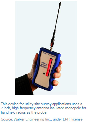
A handheld device for remote contact voltage detection several feet away from energized objects was developed by EPRI as an experimental prototype and then made commercially available (see figure below) for utility site survey applications. A handheld unit, like this one, based on capacitive detection responds to the electric field established between the energized object and the ground.
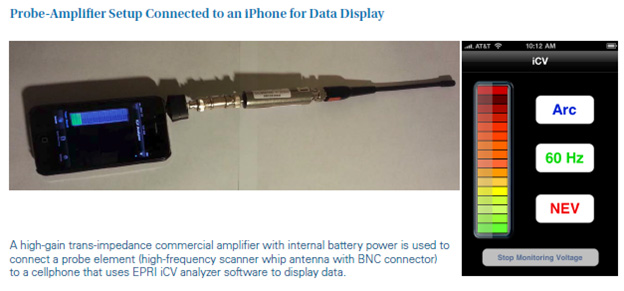
Another EPRI innovation, the iCV analyzer software implemented on an iPhone was tested as a remote detector display system using the microphone audio input. A high-gain trans-impedance commercial amplifier with internal battery power (Omega Inc.) was used to connect to a probe element (an antenna in this case). The setup is shown in the figure below.
Many urban utilities are mandated to address the public risk of electric shock through periodic scanning of publicly accessible areas to identify unintentionally energized objects. Experience shows that scans and tests must be repeated periodically to account for changes such as electrical rework, circuit loading, and intermittent contact of a faulted conductor.
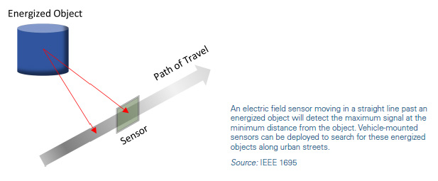
To address these concerns, technology exists that enables utilities to cover more territory much faster by means of detecting the electrical fields emanating from these energized objects while passing a vehicle-mounted sensor throughout the urban streets. The principle is illustrated below. An electric field sensor moving in a straight path past an energized object will detect the maximum signal at the minimum distance from the object.
When the mobile scanning equipment alerts the crew of a potentially energized object, someone must manually check the voltage on exposed metal objects in the area. If the condition is considered hazardous, the object must be isolated from the public, sometimes by an attendant, while a work crew is dispatched to remedy the issue.
Although vehicle-mounted electric field sensors greatly increase the efficiency in which urban streets can be scanned, the limitation to this approach is the necessity to have navigable roads that are near the contact voltage hazards. The potential exists for hazards that are beyond navigable roads, such as boat docks, marinas, fountains in retention ponds, urban parks, playgrounds, stadiums, community ballparks, and any area where floodwaters make thoroughfares impassible. Presently, detecting contact voltages at distances greater than approximately 30 feet away from a navigable roadway requires travel on foot and manual measurement.
Objectives
Defining the objectives of the investigation will define the procedure to be followed. The generic objectives are as follows:
- Energized object survey: When the objective is to quickly assess the absence of electrically energized objects throughout a service territory, the requirement is fairly simple, requiring only recording forms and voltage indicators or voltmeters.
- Voltage source or level quantification survey: When complaints are received or an energized object is detected during a routine survey, more detailed investigation is typically useful to ensure that statistical objectives may be met when analyzing the information from a database. More detailed recording forms plus instrumentation capable of voltage and or current quantification are required.
Figure 8 shows how to measure the voltage between a metallic pole and a remot earth reference point.
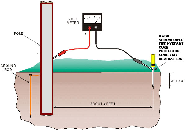
Figure 8
Measuring Voltage Between a Metallic Pole and a Remote Earth Reference Point
Defining the objectives of the investigation will help define the equipment, materials, and documentation necessary. The requirements will be different depending on the type of complaint. When complaints are received or an energized object is detected during a routine survey, a more detailed investigation will help quantify the source, the mode of energization, and the possible mitigation options. More detailed recording forms plus instrumentation capable of voltage and/or current quantification may be required. When the energization is due to a magnetic induction source, the objectives fall more in line with the assessment procedures for residential investigations.
Suggested Equipment and Materials
- Non-contact AC voltage indicator
- High-impedance true RMS AC multi-meter
- Harmonics analyzer (optional)
- T-Handled twist-type grounding rod or large screwdriver
- Paint scraper
- Recording forms
- Watch
- Personnel protective equipment
- Digital camera
- Wire spools
- Load resistors
- Electricians tool box
- Shovel or gardening spade
Measurement Procedure When Gravel or Earth Is Readily Available
This process is applicable to most metal objects such as poles, service box covers, and manhole covers. Refer to Figure 9 through Figure 12 for visual references.
- Using an operational non-contact voltage indicator, position the unit within 6 inches of the object under test. If the unit indicates the presence of a voltage, go to step 2.
- Push a metal screwdriver (or a temporary grounding device) into the earth to a minimum depth of 3 inches or until a good solid earth contact is made, approximately 4 feet away from the metallic object. Note: When pushing the screwdriver into the ground, do not let it contact other metal objects such as ground rods, down guys, primary and secondary cables, metal pipes, or any other obstructions that might influence the voltage measurement.
- With a high-impedance AC voltmeter, measure the voltage from the grounded connection to the suspected energized object.
- Record the measurement and the time when it was taken.
- If accuracy of the reading is an objective, move the ground connection 45 degrees around from its initial location, push it into the ground, and take another voltage measurement to verify the first one. If the readings are not the same, then move the ground connection until a stable reading is obtained.
- Record the second measurement and the time when it was taken.
- If the source is not readily identifiable, repeat steps 3 through 5 to obtain a DC voltage reading and spectral content.
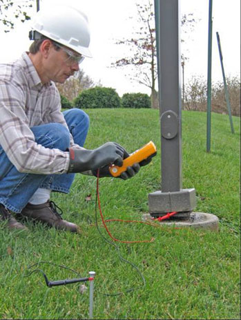
Figure 9
Sample Measurements Between a Metal Light Pole and a Reference Ground
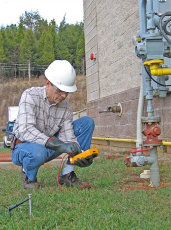
Figure 10
Sample Measurements Between a Gas Service Point and a Reference Ground
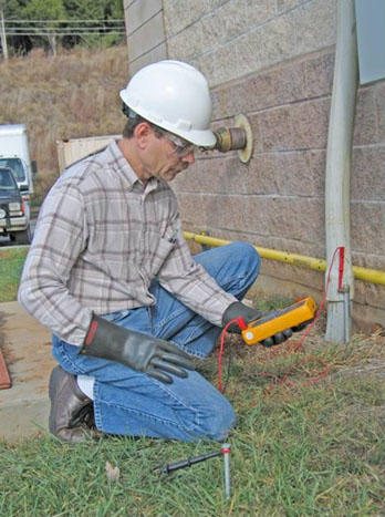
Figure 11
Sample Measurements Between a Grounded Meter Base and a Reference Ground
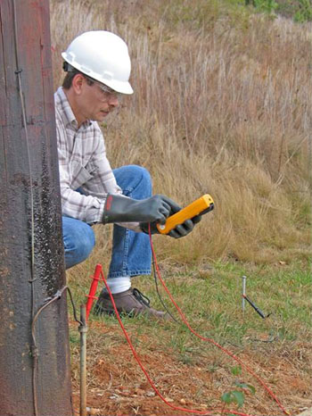
Figure 12
Sample Measurements Between a Pole Down Ground and a Reference Ground
Procedure for Urban Investigations (No Gravel or Earth Readily Available)
These measurement steps are the same as the prior section with the exception that in urban areas where gravel or earth is not readily available, the investigator will not drive a rod or screwdriver into the earth but instead will need to find one or two suitable grounded metallic connection points that are assumed not to be energized. Neutral conductors, curb protectors, water pipes, and fire hydrants are generally considered to be well-grounded objects. The non-contact voltage indicator is also useful for identifying objects that can be used to gain confidence in the object to be used as the ground reference.
Useful Documents, References, and Links to Measurement Procedures and Equipment
- Protocols and Practices for Stray Voltage Testing, T. C. Surbrook, J. R. Althouse, K. G. Tinsey.
- Neutral to Earth Voltage and Urban Stray Voltage Measurement Protocols: Test Equipment and Procedures, EPRI 1010652.
- Effects of Electrical Voltage/Current on Farm Animals: How to Detect and Remedy Problems, United States Department of Agriculture, Agricultural Research Service, Agricultural Handbook Number 696, December 1991.
- Power System and Railroad Electromagnetic Compatibility Handbook, Revised First Edition, EPRI, Palo Alto, CA, Oncor Energy Delivery Services, Dallas, TX, The National Grid TranscoCompany, Warwick, UK, Association of American Railroads (AAR), NW, Washington DC and American Railway Engineering and Maintenance-of-Way Association (AREMA), Landover, MD: 2006. 1012652.
- EPRI Technical Brief 1000068: Pool Shocking: "Fun in the Sun" Can Be a Shocking Event, EPRI, Palo Alto, CA: 2000.
- IEEE Standard 1100-2005, Recommended Practice on Powering and Grounding Electronic Equipment.
- NFPA 70E-2004, Standard for Electrical Safety Requirements for Employee Workplaces.
- CFR 29, Part 1910, Occupational Safety and Health Standards (OSHA), U.S. Department of Labor, 2006.
- CFR 29, Part 1926, Safety and Health Regulations for Construction (OSHA) , U.S. Department of Labor, 2006.
- Accredited Standards Committee C2-2002, National Electrical Safety Code (NESC).
- NFPA 70-2005, National Electrical Code® (NEC®).
- ANSI/NSPI-5 2003, American National Standard for Residential Inground Swimming Pools.
