Using the Fluke Scopemeter to Investigate Stray Voltage
Introduction
Complicated stray voltage investigations usually cannot be accomplished with just a standard true-RMS voltmeter. Oftentimes, the key to understanding and diagnosing the source of a stray voltage problem is the use of metering equipment capable of analyzing the spectral content (harmonics) of the contact voltage waveforms. Electric utilities such as Consolidated Edison (NY), Central Hudson (NY), We Energies, Southern Company, Tennessee Valley Authority, and Snohomish County PUD have begun to consider waveform analysis and spectral content as part of their investigative approaches. One tool that measures and graphically presents waveforms and spectral content is the Fluke Scopemeter, shown in Figure 1.
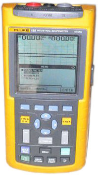 |
| Figure 1: The Fluke Scopemeter |
Operation of the Scopemeter
While the Scopemeter series of instruments have some variation in menus and functions, the overall procedure is as follows:
- Using a standard set of multimeter test leads (and an appropriate load resistor), go to the MENU options and select “SCOPE/METER.”
- Set up the appropriate channel (A or B) to measure AC Volts and then select the 1:1 probe option.
- Press the HOLD/RUN button on the Scopemeter and make sure that the meter is in “AUTO” mode.
- Measure between the two contact voltage points and press “HOLD/RUN” to freeze the waveform on the Scopemeter screen.
- Press the SAVE/PRINT button on the meter and store the waveform to one of the memory slots.
- Press the MENU button on the meter and select the “HARMONICS” menu option.
- Press the HOLD/RUN button on the Scopemeter and make sure that the meter is in “AUTO” mode.
- Press the VOLT/AMP/WATT control button and make sure that the meter is on the “VOLT” setting.
- Measure between the two contact voltage points and press “HOLD/RUN” to freeze the harmonic histogram on the Scopemeter screen.
- Press the SAVE/PRINT button on the meter and store the harmonic histogram to one of the memory slots.
All waveforms and waveform data are downloadable to a PC via the Fluke Scopemeter software.
Example Measurements Using the Scopemeter
Electric Induction-Related Voltage Source
Electric fields emanate from charged conductors and objects anytime that they are energized. As opposed to the magnetic field, which requires current flow, the electric field is always present on an energized conductor.
Characteristics of this type of contact voltage include:
- The electric field is generally not a concern except at transmission-class voltage levels of 69 kV and higher.
- The electric field is capacitively coupled to conductive objects such as metal roofs on buildings, pipelines, fences, light poles, and so on.
- Unlike the magnetic field, which varies in intensity, the electric field tends to remain fairly constant over time. This provides a useful way to distinguish between electric and magnetic field sources, even though the voltage waveforms can look fairly similar in some situations.
Figure 2 shows a Scopemeter measurement of a contact voltage caused by electric induction of a fault.
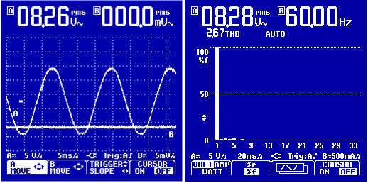 |
| Figure 2: Scopemeter Waveform of a 60-Hz Fault Voltage (Left) with Minimal Harmonic Content (Right) |
The Neutral-to-Earth Voltage (NEV) Current Source
A good example of a current source is the voltage drop created on a neutral conductor when AC current flows through the impedance (resistance) of the conductor. Most codes allow for about a 3% voltage drop on a single-phase electrical circuit. It follows that half of that three percent would be on the neutral conductor, while the other half of the drop is on the phase conductor. This means that the expected voltage drop on a typical neutral conductor is going to be 1.5% or just under 2 volts when the circuit is fully loaded.
Characteristics of this type of contact voltage include:
- The voltage measured at the contact location will look exactly like the load current (which is the current source). The contact voltage will be sinusoidal only if the load current is sinusoidal, whereas the voltage drop will be high in harmonic content if the load current is high in harmonic content.
- The only time one would expect to see a sinusoidal waveform from a neutral current source would be if the load were either a motor (pump, fan, and so on), a heater, or an incandescent light bulb. Nearly all other loads would create some amount of harmonics (typically greater than 10% THD).
- Unlike the fault condition where the voltage should remain fairly constant unless the weather changes from wet to dry or vise versa, the neutral voltage drop measurement will go up and down as the current on the circuit goes up and down.
Figure 3 shows a Scopemeter measurement of a contact voltage caused by an NEV current source.
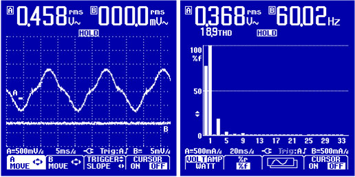 |
| Figure 3: Scopemeter Waveform from an NEV Source Containing DC, Third, and Fifth Harmonics |
Magnetic Induction
Electromagnetic fields are present any time that there is AC current flowing through a circuit conductor. As such, the magnetic field will couple onto any conductive objects in parallel with the conductor that is generating the magnetic field. Common situations where an object becomes energized include buried water and gas lines as well as fences and railroad tracks.
Characteristics of this type of contact voltage include:
- The magnetic field will couple onto conductive objects in parallel with the current-carrying conductors, impressing a voltage onto the object that looks exactly like the current on the neutral conductor.
- While it would follow that the neutral-to-earth voltage at any of the pole down grounds would have a similar waveform (but different magnitude), they should be electrically out of phase with one another by ninety degrees.
- Depending on grounding of the neutral and the grounding condition of the pipeline, as well as the possibility to have combined electric field coupling, magnetic induction, and even earth current conduction, the NEV and the pipeline-to-earth voltage waveforms may or may not look identical on a scope meter.
Figure 4 shows a Scopemeter measurement of a contact voltage caused by magnetic induction.
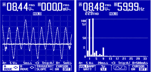 |
| Figure 4: Scopemeter Waveform from a Gas Pipeline Containing a Third and Ninth Harmonic |
