Application and Use of Load Resistors in Contact Voltage Assessments
Introduction
When assessing contact voltages, the recommended practice is to select a load resistor that represents the minimum body path resistance of the person or animal that could potentially be impacted by the contact voltage condition. The load resistor is used to bridge the gap between the contact points, thereby creating a representative current flow (I) through the path that is equal to the measured contact voltage (V) divided by the resistor (R) value (I = V/R).
Selecting a Load Resistor
Using the load-resistor methodology, the measured voltage is meaningful in terms of understanding perception, reaction, and fibrillation potential of the source. Selection of a suitable load resistor involves several important considerations:
- Appropriate wattage rating for the resistor (maximum expected V2 divided by R) Source impedance with the load resistor
- Earth resistivity in series with the load resistor
- Contact resistances in series with the load resistor
Considering Soil Resistance
Soil resistance plays a part in the amount of contact voltage that will be applied to the load resistor. EPRI set up a test using a variable voltage source and different soil compositions with varying levels of moisture. The basic idea was to understand how much impact the series resistance and impedance components would have on the measured voltage when using different values for the load resistor ranging for 100 ohms to 20,000 ohms.
The following figures summarize the test results:
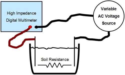 |
| Figure 1: Soil Composition Test Setup |
As shown in Figure 1, the test setups are configured so that the different jars of soil can be tested dry, then gradually moistened to better understand two key aspects of taking field measurements.
The first aspect is how the physical soil composition impacts soil resistivity (typically represented in ohms per meter). The resistivity of the soil subsequently impacts the voltage reading because that resistance is going to be in series with either the body or the representative load resistor. The second aspect is how the voltage readings change as soil resistivity and moisture either increase or decrease the Thevenin equivalent resistance (looking back into the voltage source).
A subtle but important source identification concept can also be observed using this test setup. The observation is that the magnitude of the voltage may change considerably as the resistance of the circuit path varies, but the frequency and waveform do not. Therefore, the spectral content is a very useful tool for source identification.
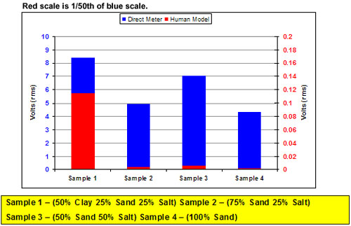 |
| Figure 2: Dry Sample Meter Readings with and without 1-kOhm Load Resistor |
The significance observed in Figure 2 is that the load resistor is extremely important for dry or rocky soil in that no current can flow through a body path if the voltage goes away when the load resistor is applied. The red histograms show the voltage when the load resistor is used, and it is clear that even with soil sample 1, only about one tenth of one volt was measured with the load resistor. This would suggest that only 0.1 milliamps of current flow between the two electrodes shown in Figure 1.
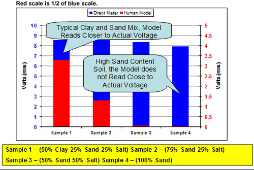 |
| Figure 3: Wet Sample Meter Readings with and without 1-kOhm Load Resistor |
The significance observed in Figure 3 is that even with wet soil, the load resistor is extremely important for determining the amount of current that can flow through a body path. The red histograms show the voltage when the load resistor is used, and it is clear that even with the wet soil samples, there is a significant voltage difference as compared to using no load resistor. A second observation is that the soil composition can have a major impact on the amount of current that can flow through the same type of energization path (where the clay mixture was the most conductive and the 100% sand sample was the least conductive).
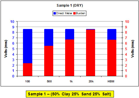 |
| Figure 4: Dry Sample Meter Readings with Different Resistor Values |
As shown in Figure 4, testing on one of the dry soil samples with different load resistance clearly shows that the load resistor value can impact the voltage measurement when there is additional resistance in the circuit path. In the case of the 100-ohm resistor, the impact is nearly a two-thirds reduction in voltage. In the case of the 500-ohm resistor, the impact is about a one-third reduction in voltage. In this case, we are testing with a Variac; thus the source impedance is low. This suggests that the soil resistance is somewhere in between these values. To determine the actual soil resistance, we can compare the open-circuit voltage (VOC) reading to the voltage reading with the resistor (VR) as follows:
- Measure without load and record the “no load” or “open circuit” voltage reading, VOC.
- Measure with a load resistor and record the “loaded” voltage reading, VR.
- Calculate the series resistance voltage drop (VS) as VOC - VR.
- Find the net series resistance, RS, from the relationship:
 |
Manipulating this relationship we find: RS = (VOC - VR) x RL / VR
Conceptually, Figure 5 describes the previous discussion and corresponding equations.
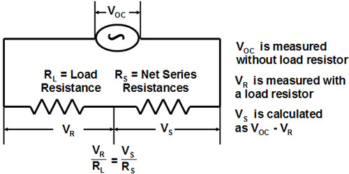 |
| Figure 5: Process for Determining Series Resistance - Using a Multimeter and Load Resistor |
Now, using the measured values in Figure 5, we can approximate the resistance of the soil sample (RS) by selecting any of the resistor values and making the calculation. For example, using the 500-ohm resistor (V500 = VR) we find that the series soil resistance between the electrodes (VS) is:
(8.6V - 5.5V) x 500 ohms / 5.5 V = 282 ohms
Repeating this with the 100-ohm and the 1 k-ohm load resistor, we find the soil resistance values to be: (8.6 - 2.25) x 100 / 2.25 = 282 ohms and (8.6 - 6.7) x 1000 / 6.7 = 284 ohms.
Rounding these values, we find the dry soil resistance of the sample under test in Figure 4 to be approximately 280 ohms, and we also find a useful method to determine the net series resistance of the circuit path.
Proper Watt Ratings for Load Resistors Used in the Contact Voltage Investigation
To expand on the conclusions from last year’s document “2008 Research Update and Guidebook Materials, EPRI, Palo Alto, CA: 2008 1016047,” when attempting to measure a source with a load resistor, it is necessary to ensure that the current flow through the circuit will not damage the load resistor. The proper watt rating may depend on whether or not the expected source voltage is due to a 60-Hz fault or is due to an inadvertent energization. The safe watt rating needed for a load resistor is calculated as follows:
 |
Where:
Vmax is 125% of the maximum expected circuit voltage
R is the value of the load resistor in ohms
The safe voltage rating for an existing wattage rating and resistor is calculated as:
 |
Where:
W is the actual wattage specification from the manufacturer data sheet
R is the color code specified resistor value
sqrt is the square root of the value in parenthesis
V is the maximum allowable voltage that the resistor can be used on
For example, on a 120-volt circuit using a custom 500-ohm and a custom 1 k-ohm resistor, the minimum wattage ratings would be 1502/500 = 45 watts and 1502/1000 = 22.5 watts. Similarly, assuming a plus/minus 10% tolerance, the 470-ohm ¼-watt resistor could be used on voltages not exceeding (470 ohms * 0.9 * 0.25 watts)sqrt = 10.3 VRMS and the 1 k-ohm ¼-watt resistor could be used on voltages not exceeding (1000 * 0.9 * 0.25)sqrt = 15 VRMS.
The following table provides some general guidelines for application of load resistors to ensure proper wattage ratings:
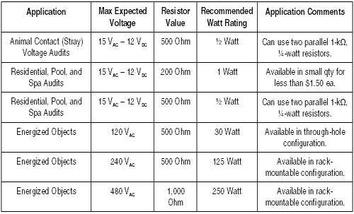 |
| Table 1: Load Resistor Ratings |
 |
| 1,000-Ohm Resistors with Different Power Ratings (1/4 Watt, 1.0 Watt, 10 Watt, and 100 Watt) |
The point of interest here is that the safest methodology is to use a wattage rating at least 125% of the maximum watt dissipation expected if the maximum possible source voltage were present. The field investigator can accomplish the load test objective with a resistor with a much lower watt rating if the investigator has a little application knowledge and understands that the load resistor can exceed the specified watt rating for several seconds without overheating but should not be left across the circuit for more than approximately five seconds.

